


Temporary Shoring Engineering Services
Adept Construction Solutions Inc. Temporary Shoring Design Package
Foundation Engineering is substantially different from shoring engineering. In some cases, when serpentine or sandstone or medium to hard clay formations are present, shoring design values and criteria are not taken into consideration correctly which results in unreasonable costly, more difficult and time consuming shoring design.
ACS will review existing soil reports, create shoring concept design that is based on our vast knowledge of soil and rock conditions.
We evaluate constructability, means and methods, site limitation and access as well as adjacent structures to come up with most cost effective and structurally reasonable shoring plan.
Adept Construction Solutions can include the following:
- Geotechnical Amendment for Temporary Shoring;
- Site Evaluation;
- Shoring Design Concept;
- Preliminary R.O.M. (relative order of magnitude cost);
- Full set of drawings for DBI submittal;
- Set of Structural Load and Surcharge Calculations for DBI;
- Expedited Permit Services.
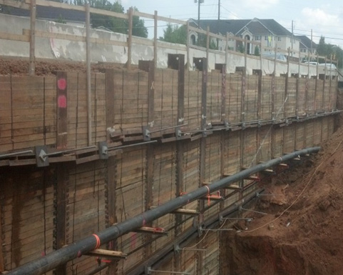
Soldier Beams and Lagging
Soldier piles (beams) and lagging is an excavation support technique where vertical piles (most commonly steel piles either driven or lowered into a drilled excavation and grouted) are at regular intervals along the proposed wall location. Wood lagging (sometimes steel or concrete panels) is placed between the soldier piles as excavation proceeds (typically in 3-ft to 5-ft increments). For excavations of small height, the walls are typically cantilevered.
The walls can be tied-back or braced where additional lateral support is required, such as tiebacks.
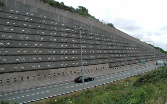
Tiebacks
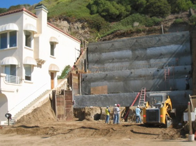
Tiebacks may be used in conjunction with a variety of retaining systems (sheet piles, soldier piles, secant and tangent walls to provide additional lateral resistance beyond that achievable by a cantilevered wall.
Tiebacks are drilled into the ground with a small diameter shaft.
The tie-backs are constructed of thread bar or steel strands which is inserted into the small drilled excavation. The shaft is grouted which encases the steel and bonds it to the surrounding ground.
The steel is stressed to a design load and locked-off to maintain the load on the tiebacks.
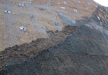
Soil Nails
Soil Nails are an excavation support system where the nails are drilled (typically at an angle) through mesh face into the earth to pin it back.
The nails are installed as the soil is excavated, usually in 5-ft lifts.
Customarily, shotcrete is sprayed over the final nail and mesh combination to provide the finished wall.
Soil nail and shotcrete walls can be used for temporary or permanent support.
Rock Anchors Tie-downs
Rock anchors and Tie-downs are installed in a similar process to Tie-backs however are typically installed vertically to provide resistance to uplift forces on a structure (often due to hydrostatic forces from a very high ground. They can be horizontal but are typically installed at an angle of 15 to 45 degrees.
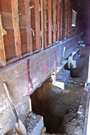
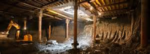
Underpinning
Underpinning is a construction technique to strengthen or support the foundation of an existing facility, often in conjunction with new, adjacent construction or after a significant natural hazard event (e.g. earthquake). Underpinning may consist of hand-dug pits filled with concrete (see right), piles with brackets supporting below the foundation (see left), micropiles and bracing.
Micropiles for Underpinning
Micropiles are deep foundations that are 12 inches or less in diameter although typically they have a diameter between 3 to 10 inches.
They are typically constructed with steel casing and/or threaded bar and high-strength cement grout. Micropiles are most commonly made up of high strength steel casing and rebar, but can also be installed in some conditions with hollow-bar systems, which are stabilized with pressure grouting in lieu of casing.
Capacities vary depending on the micropile size and subsurface profile. Installation can be achieved by rotary drilling, augering, driven or vibrating tooling.
Micropiles are particularly efficient where natural or man-made obstructions occur, in limited access or low-headroom conditions and in karst geology where rock surfaces are erratic and large voids are typically present. They can typically be designed to resist compression, uplift and lateral loads and have been used to support a variety of facilities.
Installation techniques can be tailored to ensure minimal damage to existing foundations and to allow facility operations to be maintained during construction. Micropiles are often used to support very large capacities with little or no movement of the foundation.
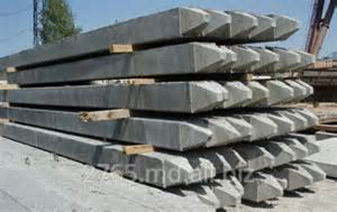
Driven Piles
Driven piles are prefabricated deep foundations driven into the ground with a pile driver to a design depth or resistance. Driven piles are typically made of timber, precast reinforced concrete, or steel. Steel piles are usually either h-beams or circular steel pipe. Precast concrete piles are most often available in square, octagonal, and round cross-sectional shapes and are usually pre-stressed and reinforced with rebar.
Compacing Grouting
Compaction grouting is a ground improvement/reinforcing technique where a specific volume of grout is placed at discrete intervals in the ground to provide a known displacement of granular soil or reinforce soft, fine-grained soil. The technique is also commonly used to stabilize sinkholes and other voids/cavities in the subsurface. A small diameter steel casing (typically less than 6-in diameter) is advanced to the lowest level of the zone of improvement. A low-slump grout is pumped at high pressure to place a pre-determined volume of grout to provide a design displacement of the in-place soils. The casing is then raised at specific increments with grout injected at each increment. The result is a column of grout through the improvement zone. This is repeated at planned injection points across a project site. Compaction grouting can increase allowable bearing pressure and decrease settlement for shallow foundations and mitigate liquefaction potential.
Pressure Grouting
Pressure Grouting is the process of pumping a cement or chemical grout into soft or weak strata of soil or voids. This grout fills these voids, thus stabilizing and strengthening the soil. Pressure Grouting has many applications. One of these includes support for existing structures or where foundations have shifted.
| 1 | The purpose of Pressure Grouting is to control the amount of grout going into the pipe. As the process is repeated at additional elevations, the soil is compacted. |
| 2 | The process begins with the pumping of grout at the lowest elevation. The pipes are withdrawn slightly and the grout is allowed to set. |
| 3 | The process is repeated at the next elevation. Upon completion, the pipe is again withdrawn slightly to the next elevation. The grout is allowed to set. Each level of grout pumping will push the soil upward. |
| 4 | The number of grout pumping at these different elevations that are needed to compact the soil will vary. Once the soil is compacted, it causes lift. This lift then pushes the footing and wall upward. |
Top- Down Construction

Top-down construction is a method used for deep excavation systems. It is different from the conventional bottom-up construction method, in that it requires erecting and constructing floor slabs right after each excavation.
In some instances top-down construction may have benefits but it will also have certain drawbacks. In order to fully understand top-down construction one must go through the technique step by step.
Top-down is particularly advantageous for construction of high-rise buildings in congested area. Another merit for top-down construction is that it shortens the construction period due to the simultaneous construction of the basement and the superstructure. In some instances the owner insists on using this method because of scheduling purposes.
Additionally, considering San Francisco location, a project which has an extensive excavation period would most likely end up costing much more than one which has a fast innovative excavation system. Furthermore, structurally, the high stiffness of floor slabs increases the safety of excavation, making it better than steel struts.
Drawbacks of top-down construction are cost, construction period of basement, and in some instances construction quality. One of the main drawbacks of using this method is that it is highly costly, due to the construction of pile foundations. If soft soil layers are encountered, there may be lateral displacement of the retaining walls, and this can be a problem.
Because the construction period of the basement is lengthened for this sort of a method, creep may occur leading to ground settlement. The typical construction procedure is a nine step procedure, and is shown in detail on the following page. The first step is to construct the retaining walls (perimeter walls). Once the retaining walls are constructed, you construct the piles, and place the steel columns where the piles are constructed. After the piles are placed, the first stage of excavation begins. Step four involves casting the floor slab of the first basement level. Then we proceed to the second stage of excavation and de-watering. Next, we cast the floor slab of the second basement. Depending on the depth of the basement, one can repeat the same procedures. The last two steps involve constructing the foundation slabs and ground beams in order to complete the basement.